|
|
|
Telecommunication engineering
Fibre Optics
Ronan Allibert
BSc in Electronic and Electrical Engineering
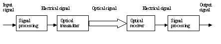
A basic optical fibre communication system is composed by a signal processor which code the intelligence of a signal, an optical transmitter which initiates the optical signal according to the optimised electrical signal, a fibre to transmit the optical signal, a detector which receives it and convert it into a coded electric signal, and finally a decoder to recover the signal intelligence.
Signal processing
Input/output signal processing is handled in the same manner as a conventional communication system. On the transmitting end, the circuit typically consist of a multiplexer, modulator or encoder. This circuit processes the input signal or modulates the intelligence prior to transmission. The receiving end of a link has a demultiplexer, demodulator or decoder.
Any type of information can be transmitted over a fibre optic communication link (analogue or digital). Due to noise, attenuation and non linearity of the system… precautions must be taken.
The multiplexer is a signal processing circuit. It is the ideal form of communication for a fibre optic link. It takes advantage of the digital qualities of fibre optic and adds multiple channel capability to a single channel. Many types of multiplexing are adaptable to fibre optic communication. We will now focus on TDM (time division multiplexed).
Multiple data inputs can be multiplexed into a single time division multiplexed (TDM) output for transmission. Multiplexing is controlled by a phase locked loop, a frequency divider, and a binary counter. The phase lock loop determines the multiplexing rate and circuit synchronisation.
Principle of the multiplexer studied:
The 4 inputs are sequentially sampled. A multiplex frame is then generated. Within each multiplex frame, 4 binary counts generate 4 sequential time slots. During each time slot, the 4 signal inputs to the multiplexer are sequentially applied to the single data output line.
The section of the fibre optic communication system that distinguish it from a conventional system are the optical transmitter, the fibre optic cable, and the optical receiver.
The optical Transmitter
The optical transmitter contains circuit used to convert electrical input into an optical output for transmission over the fibre optic cable. The transmitter in a fibre optic system is a light source. To be practical, fibre optic system light sources must be small, capable of high modulation rates, exhibit narrow spectral properties, have high radiance, provide adequate power, have long life, and be rugged.
Two semiconductor devices which fill these requirements are the LED and the laser diode. Both devices exhibit properties that make each preferable in given applications. Briefly, however , the LED is useful in low cost, low power, short distance circuit. The laser diode is used in long distance communication systems, because of its higher power.
LED fibre optic transmitter
Since semiconductors are current operated devices, increasing the amount of forward current through the diode causes an increase in optical power. Varying the forward current of a LED with a modulation signal impresses intelligence on the emitted light. When placed next to the end of a fibre optic cable, some of the modulated light from the LED will be coupled to the cable. Optical power that is not coupled into the cable is lost. Coupling loses occur at both ends of cable and at interconnecting points. Lost power must be replaced by increasing the transmitter output.
Coupling losses can be divided into two categories : extrinsic and intrinsic. Intrinsic losses result from imperfections in the optical characteristics of the cable and affect the propagation of the light through the fibre. Extrinsic losses arise from complications in aligning and maintaining alignment of the optical path.
Extrinsic losses are of primary importance in the construction of cable connections and in splicing broken fibre. Common types of extrinsic cable losses between two cables are : axial displacement, end separation, angular misalignment, irregular end finish, fibre distortion or size difference.
The light power of the transmitter is determined directly or indirectly. Directly : using a test instrument such a bolometer, indirectly : by measuring other parameter with a photodetector for example, knowing its sensibility.
The sensibility (conversion gain or CG) of a photodector is determined by dividing an applied given power light signal by the output voltage.
The fibre optic cable
A fibre optic cable has a central core and an outer clad. Both parts are made from materials that give the optical fibre its ability to redirect light back toward its centre to keep the light escaping through the sides. This technique is known as total internal reflection (TIR). The basis for TIR in a fibre optic cable is the index of refraction of its optic parts: the core and the cladding.
The core of a fibre has the higher index of refraction. Light rays in the core are of primary importance, they carry the intelligence.
Beyond a critical angle, all light rays are reflected at the boundary of the core and the cladding, hence the intelligence carrying light is propagated the full length of the cable.
An optical fibre consisting of a core and a clad with fixed but different indices of refraction is termed a step-index fibre. Optical fibres are also constructed using variations of the step techniques. One variation makes the refractive index decrease from the centre of the core outward. This is called graded-index fibre. Another techniques makes the core so small that only a single ray can travel through it. This is known as the single mode fibre.
Each type has its advantage and disadvantages in given applications. Briefly, the step mode fibre is the cheapest and easiest to terminate but has a narrow bandwidth, the graded index fibre is more expensive but has a wider bandwidth. The single mode fibre is the most expensive, but has the widest bandwidth, it should be driven by a laser diode.
Acceptance angle is the greatest angle from which a beam of light can enter the fibre optic cable.
Numerical aperture is a number that shows how well a given fibre optic cable will collect light.
(The sine of an acceptance angle is numerical aperture)
N.A. = sin(
?A) =The minimum of angle for TIR is called the critical angle.
Fibre optic receiver
The receiver in a fibre optic system is a light sensitive semiconductor with the ability to cause current flow when struck by light. Two light sensitive semiconductor devices in common use in fibre optic systems are the PIN photodiode and the APD (avalanche photodiode). Each device has characteristics that make it preferable in certain applications. The PIN diode used primarily in low-cost, short link systems; The APD is more expensive, higher efficiency, and is more appropriate for long distance links.
If the opening in the diode surface is made to correspond to the size of the core of s fibre optic cable (similar N.A.), and the cable is placed close to the opening, the light transmitted by the cable modulates the reverse current. Thus, the light beam and the intelligence on it are converted from optical energy to electrical energy.
Optical power that is not coupled into the photodetector is lost and serves no useful purpose. If enough power is lost, the diode may not generate a corresponding current flow, which would result in lost data. Power losses, however can be compensated for by increasing transmitter output power.
The function of a fibre optic cable is to provide a transmission medium for optical signals. As with any method used to channel energy from one area to another, losses also occur in this transmission medium. For example, microbending is the loss of light energy due to changes in temperature of the fibre optic cable. The most important loss comes from the cable itself. Cable attenuation loss is rated as loss per unit length.
summary
Specially processed plastic and glass fibres be formed into optical cables to propagate light frequencies over long distances.
Total internal reflection (TIR) is the technique used to confine light rays to the core of a fibre optic cable.
In a fibre optic link, electro/optic signal conversion is performed by light emitting and light receiving semiconductor devices.
The optical characteristics of the elements in Fibre Optic circuit must be matched for maximum efficiency.