|
|
|
Telecommunication engineering
Digital Modulation
Ronan Allibert
BSc in Electronic and Electrical Engineering
Communication is the transmission of information between two distant points. To ease the transmission between the two points, depending on the constraints of the communication system, the information may be modulated. In this report we will have a look at the digital modulation techniques.
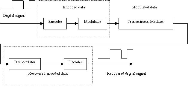
A digital signal consists of series of pulses representing the intelligence is input to an encoder. The encoder changes the digital signal into another form (encodes data) that optimises it for use in the system. The encoder output is then input to the modulator, which transmits a varying signal proportional to the encoded data over the channel or transmission medium. A channel consists of a single conductor, telephone lines, or air.
The decoding process of the receiver operates in reverse. The demodulator receives the transmitted modulating signal and recovers the encoded data. The decoder then recovers the digital intelligence from the encoded data, which resembles the original transmitter digital intelligence.
The roles of the encoder and the modulator are similar: they prepare the intelligence signal for a more efficient transmission, by changing its shape.
Encoding/decoding
Non-return to zero (NRZ), return to zero (RZ) and Manchester data are three common codes used to represent the one and zeroes of a digital signal. Choice of a code to convey the binary information depends on the type of modulation and demodulation techniques, frequency response, synchronisation properties, and ease of use. No code can satisfy all categories. What distinguishes each code is how a high or low is represented for a given bit time. This is one characteristic that is given consideration in the choice of a digital code to transfer data.
The binary data for any given bit in NRZ data is fixed for the entire bit time. The binary data for any given bit in RZ is represented during the first half of the bit time. A binary one or zero will be at a 1 or 0 level respectively for the first half of the bit time. The second half of the bit time is always represented by a 0 level. This property causes transitions to occur during the midpoint of the bit time whose binary level representation is a 1. As a result, RZ data is considered a partial self-clocking code because in addition to the data it inherently contains clocking information.
Manchester data is totally self-clocking code. Manchester data contains clocking information in the data stream. A transition occurs at the midpoint of each bit time corresponding to a binary one or binary zero.
No digital code can be transferred from a transmitter to a receiver without synchronisation. When transmitter and receiver are close enough data and clock signals are sent over separate line, but when not the feasibility to connect does not exist. In this last case clock synchronisers are used in the receiver to recover a clock signal from the transmitted data. The transmitted data must contain clock information for the clock synchroniser to work properly. This limits the type of data transmitted to be in Manchester format. In this case a synchronising circuit is used to synchronise the transmitter and the receiver. The received Manchester data is sent to the demodulator/line decoder and synchroniser. The synchroniser develops a clock signal from the Manchester data synchronous to the clock signal in the transmitter. The synchroniser is first an edge detector circuit. An edge detector circuit outputs a narrow pulse for each positive and negative transition at midpoint of each bit time and at the beginning of each bit time when a transition occurs. An And gate receives the pulses from the edge detector circuit and a signal from a phase shifter circuit. The phase shifter signal is a symmetrical square wave operating at the same frequency as the clock signal output from the divided by two counter shifted 90 degrees. The phase shift signal is low each time the pulse from the edge detector circuit occurs at the beginning of a bit time. The
AND gate outputs the signal necessary for the phase lock loops to develop the clock signal. It logically Ands the output of the edge detector circuit and the phase shifter signal. By operation the output of the AND gate is high only when both inputs are high. The output of the synchroniser is input to the line decoder circuitry to recover the NRZ data.The encoder circuit consists of an and gate and an exclusive
OR gate. (RZ encoding: connected to the NRZ code and the clock, Manchester encoding: exclusive OR gate connected to the NRZ code and the clock).Noise however can disrupt synchronisation and is a concern in transferring information. Noise can cause the receiver to recover a clock signal with phase jitter. The recovered receiver clock phase varies with respect to the transmitter clock. The timing clock instability causes the receiver to sample data earlier or later than the specified time. As a result data received may be different than data transmitted. This difference between the recovered clock and transmitter clock can be resolved with the use of an elastic store. An elastic store is a data buffer. Data is written into the elastic store by one clock and read from by another. The elastic store absorbs the differences in the amount of data received when short-term instabilities exist in either clock. A simple elastic store can consist of a parallel to serial converter, a register, a parallel to serial converter an input clock (write) and an output clock (read).
The process of decoding RZ and Manchester-coded data into NRZ requires simple circuits. A D-type flip-flop can be used receiving the coded data and the clock signal. The Q output of the flip-flop represents the decoded NRZ data. The decoded NRZ data will lag the encoded NRZ data by half a clock cycle in which is not critical for communicating the data. Another method to decode Manchester data to NRZ is to use an exclusive OR gate. By using the exclusive OR gate, the NRZ decoded data is in phase with the encoded NRZ data. (Input clock + encoded Manchester data).
Modulation :
If the transmission medium is a wire linking the transmitter and the receiver the transmitted information may be in the form of NRZ, RZ and Manchester data. If transmission must take place electromagnetic properties, the bits of information are used to modulate a high frequency carrier. The choice of modulation gets its name from the way the bits are modulated. Common types of digital modulation are frequency-shift keying (FSK), phase-shift keying (PSK), and amplitude-shift keying (ASK).
Frequency shift keying is the process in which the frequency of a carrier is varied with the ones and the zeroes of the coded data. The zeroes and ones are represented by two different frequencies. The frequency used depends on the transmitter and the receiver. The amplitude and phase of the FSK signal are fixed.
A simple electronically controlled switch and two oscillators of two different frequencies can generate a FSK signal. The control input of the switch is connected to the digital intelligence signal, the level of the digital intelligence signal determines which oscillator frequency becomes part of the output.
Demodulating an FSK signal is the process of recovering the transmitted digital intelligence. The demodulating or detector circuitry must convert two different carrier frequencies of the FSK signal to recover the same digital intelligence signal bit pattern in the receiver as in the transmitter. One method of detection demodulates the FSK asynchronously to recover the digital intelligence. The detector circuitry consists of a bandpass filter, an envelope detector consisting of a full wave rectifier and a low pass filter, and a pulse shaping circuit. Another method of detection demodulates the FSK synchronously using a phase lock-loop.
Phase-shift keying is the process in which the amplitude of a carrier is varied with the ones and the zeroes of the coded data. A binary one is 180 degrees out of phase with a binary zero. The amplitude and frequency of the PSK signal are fixed.
Amplitude shift keying is the process in which the amplitude of a carrier is varied with the ones and the zeroes of the coded data. The zeroes and ones are represented by two different amplitudes. The frequency and phase of the ASK signal are fixed.
A summing junction with DC offset voltage and a balance modulator are used to generate both ASK and PSK signals. The balanced modulator multiplies the sum of the digital signal and offset voltage by the carriers and outputs the products as ASK or PSK signal. For Ask, the dc offset voltage is adjusted to add a dc voltage to the signal so that a binary 0 is above zero volts. When the digital signal is a binary 1, the carrier is multiplied by the maximum positive value of the digital signal. The product appears as the large amplitude portion of the ASK signal output by the modulator. When the digital signal is a binary 0, the carrier signal is multiplied by the minimum positive value of the digital signal. The product is the smaller amplitude of the Ask signal. On-off keying is a form of ASK in which the portion of the modulated signal representing a binary 0 is zero volts.
For PSK no dc offset is applied, making the signal polar. When the digital signal is 1, the carrier is multiplied by a positive voltage, when it is a binary 0, the carrier is multiplied by a negative voltage.
ASK signals can be demodulated using both an asynchronous and synchronous detector. PSK signals can only be demodulated using the synchronous detector.
The reference signal to the ASK/PSK demodulator in the synchronous detector must be identical to the carrier signal. The synchronous detector requires a reference signal and a product detector to recover the digital intelligence signal.